Picture Courtesy: Google
Astable Multivibrator is a two stage R-C coupled amplifier with positive feedback from output of one amplifier to the input of other amplifier.
It is a switching circuit which has no stable states as it always changes from one state to another. That’s why it got the name Astable Multivibrator.
Astable Multivibrator is also known as free running multivibrator or collector coupled Astable Multivibrator. Because it oscillates with out the aid of an external triggering signal. It is widely employed for the generation of square waves or pulses. The frequency of square wave is depends in Resistor Capacitor (RC) time constant of the circuit.
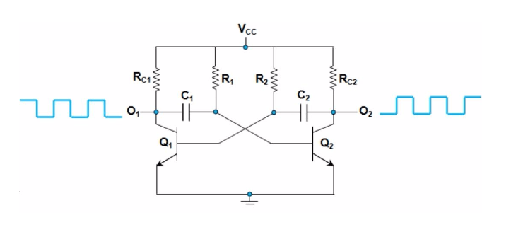
Above figure shows a typical Astable Multivibrator. Where the out put of first stage is R-C coupled to the input of second stage and the output of second stage is R-C coupled to the input of first stage.
WORKING
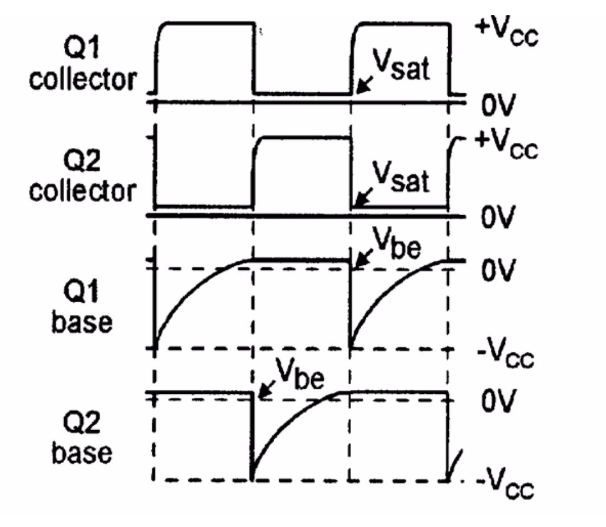
When the power gets on both the transistors starts conducting. Because of differences in their parameters and the characteristics one of the transistor will conduct slightly more.
Suppose if the transistor Q1 is conducting more than Q2, then thank collector voltage of Q1 drops to minimum and capacitor C1 starts to discharge. This negative voltage from discharging capacitor C1 fed to Q2 and it driven to cutoff. During this time capacitor C2 charges to Vcc through Resistor R, and this is fed to Base of Q1. It cause transistor Q1 to go into saturation.
After a time period determined by the time constant RC, capacitor C1 discharges completely and starts charging in reverse direction through Resistor R1. When the capacitor C1 charges to the voltage sufficient to switch ON transistor Q2, it turns ON and voltage at the collector of Q2 drops to minimum. Then capacitor C2 starts to discharge. The negative voltage from C2 coupled to Q1 and Q1 gets OFF. Then the capacitor charges to Vcc through Resistor R. This remains the transistor Q2 on saturation mode or in ON state.
When the capacitor C2 discharges completely it starts charging in opposite direction through R2. This makes the transistor Q1 ON and voltage at the collector of Q1 drops to minimum and capacitor C1 starts to discharge. The cycle then repeats itself.
FREQUENCY OF OSCILLATION
f = 1/T
T=T1+T2
T1=0.693R1C1
T2=0.693R2C2
Then
T= 0.693(R1C1+R2C2)
For symmetrical Multivibrator
R1=R2=R
And
C1=C2=C
Then
T= 2× 0.693RC
=1.36 RC
Then frequency of square wave
f=1/2= 1/(1.36RC)
APPLICATIONS
-
- Used as synchronised oscillator
-
- Used for sweep generators
-
- Used in ameture radio equipments to transmit and receive radio signals
- Used in times and systems of television broad casts and analog circuit
Created by: Technical writer Anju Radhakrishnan