Hartley oscillator is a type of LC oscillator which is widely used as a local oscillator in radio receivers. Hartley oscillator was invented in 1915 by the American engineer Ralph Hartley.
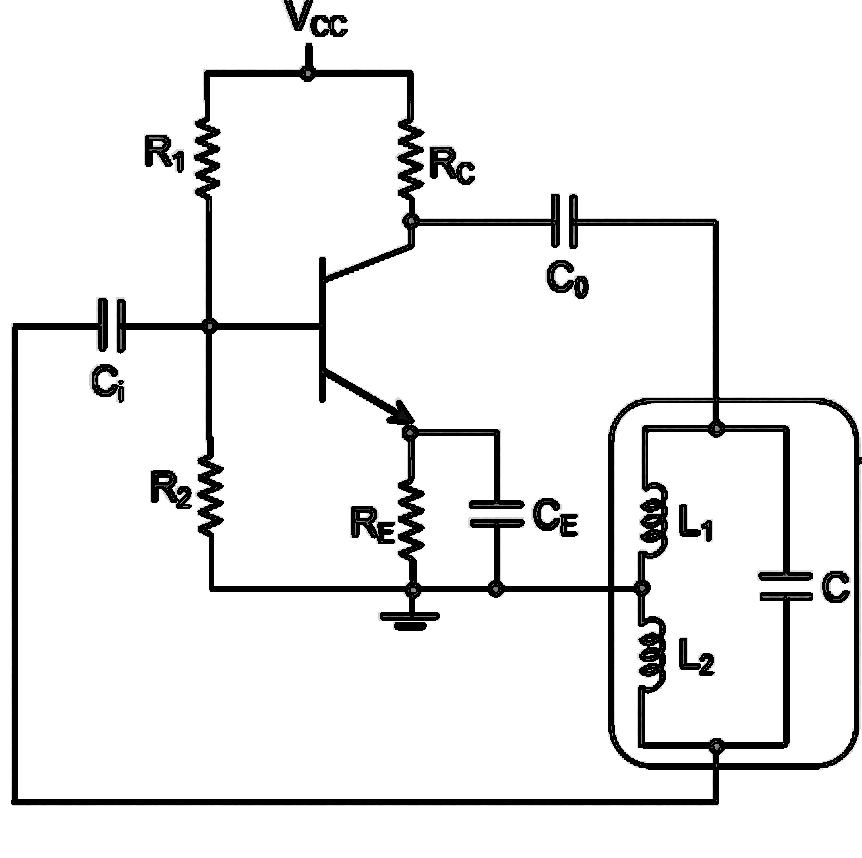
Figure shows the circuit diagram of a Hartley oscillator. It consists of single stage inverting amplifier and L-C phase shift network. The phase shift network consists of two series inductors L1 and L2 , connected in parallel to a capacitor C. The output of the amplifier is applied across inductors L1 and the voltage across inductor L2 forms the feedback voltage. The coil L1 is instinctively coupled to coil L2 , the combination functions as an auto-transformer.
Resistor R1 and R2 gives a potential divider bias for the transistor Q and parallel combination of Re and Ce provides thermal stability and bypass the amplified AC signal. A Radio Frequency Choke (RFC) is used in the collector circuit to provide a high reactance at the frequency of oscillation and a low resistance at DC to help start oscillations. The radio frequency energy developed across RFC is capacitively coupled to the tank circuit through coupling capacitor Co, which does not permits the DC currents to go to tank circuit. The output of the phase shift networked is coupled to the input of amplifier through coupling capacitor Ci.
The output of the tank circuit have 180 degree phase shift and another 180 degree phase shift is produced by the transistor. So total phase shift of 360 degree is obtained and which is very important condition for sustained oscillations
Frequency of oscillation of a Hartley oscillator is given by ,
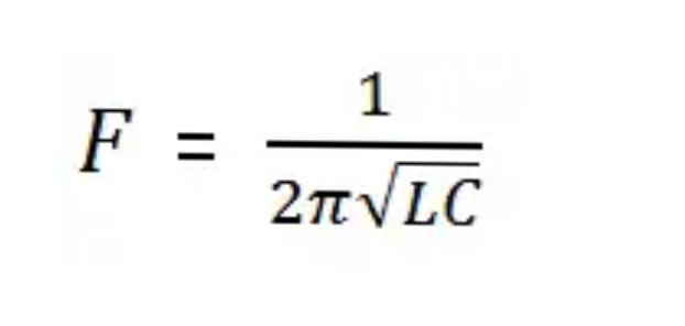
Where,
L= L1+C2+2M
M: mutual inductance
Contents
WORKING of Hartley oscillator
When the power supply is switched ON , the transistor Q starts conducting and the collector starts raising. As a result the capacitor C starts charging and when it’s fully charged, it starts discharging through inductor L1, which is inductively connected to L2. Where capacitor fully gets discharged, it starts charging again. This cycle continues and which produces oscillations in the tank circuit. Since the junction between two coils L1 and L2 are grounded, the voltage across the inductor L2 is 180 degree out of phase with the voltage across L1.
The voltage across inductor L2 is feedback to the base of transistor Q through coupling capacitor Ci. The transistor amplifies the signal and itself produces a180 degree phase shift. So the total phase shift of 360 degree between input and output is obtained, which is essential condition for producing sustained oscillation.
ADVANTAGES of Hartley oscillator
- Very few components are needed including fixed inductors or tapped coil.
- By using a variable capacitor or by varying the inductance, frequency of oscillation can be varied.
- Instead of two separate coils L1 and L2, a single coil of bare wire can be used.
- The amplitude of the output remains constant over the working frequency range.
DISADVANTAGES of Hartley oscillator
- It cannot be used as a low frequency oscillator since the value of inductors becomes large and the size of the inductors becomes large.
- The output is rich in harmonics and therefore not suitable where a pure sine wave is required.
APPLICATIONS of Hartley oscillator
- Used as local oscillator in radio receivers.
- It is suitable for oscillations in RF range up to 30MHz.
credits : Anju Radhakrishnan ( Technical writer )