Picture Courtesy: Google
Monostable Multivibrator is also called single shot or single swing or delay Multivibrator. Monostable Multivibrator is a two state amplifier with two states- one stable state and one quasi-stable state for a period determined by the circuit components and then returns to it’s initial stable state.
As only one triggering signal is required to induce a transition from a stable state to quasi-stable state and the circuit returns to it’s initial stable state automatically after a definite period. It is called single shot Multivibrator.
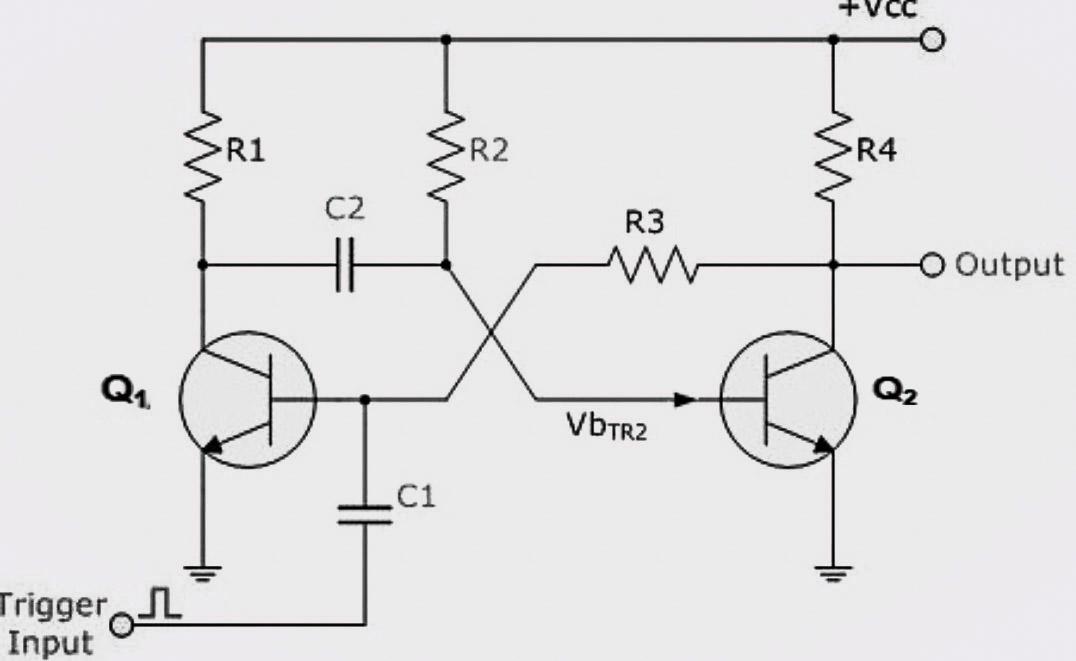
Figure shows a collector coupled Monostable Multivibrator. It have two similar transistors Q1 and Q2, and equal collector resistances R1 and R4. In stable state Q1 is in cut-off mode and Q2 is in saturation mode. The output of the transistor Q1 is coupled to the base of transistor Q2 through capacitor C2 and the output of transistor Q2 is direct coupled to the input of transistor Q1 through Resistor series R3. Trigger pulse is applied to the base of transistor Q1 through capacitor C1 to obtain the square wave.
WORKING
When the power is applied to the circuit without external triggering signal, the circuit will be in it’s stable state. That is Q1 is OFF and Q2 or ON. Capacitor C2 charges to Vcc. This condition continues until a external triggering signal is applied.
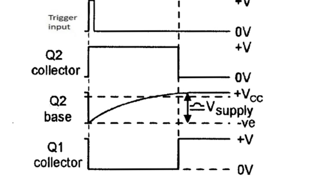
When an external trigger of positive pulse is applied to the base of transistor Q1 through capacitor C1, the transistor Q1 turns ON and voltage drop at collector of Q1 comes down to ground which was previously at Vcc. So the capacitor C2 starts to discharge and this negative voltage from discharging capacitor C2 is fed to Base of Q2 and it turned OFF. Voltage drop at collector of Q2 is rises towards Vcc and it is applied to the base of transistor Q1 through Resistor R3. This makes Q1 remains in saturation mode even if the trigger is removed. This state of circuit is called quasi-stable state.
When the capacitor C2 discharges completely, it starts charging in reverse direction through Resistor R2. When the capacitor C2 charges to the voltage sufficient to switch ON transistor Q2, it turns ON and voltage drop at collector of Q2 drops to minimum. This reduced collector voltage of Q2 fed to the base of transistor Q1 through Resistor R3, and it turns OFF. In the end transistor Q2 is saturated once again and transistor Q1 is in cut-off. That is circuit returns back to it’s original stable state. The circuit remains in it’s stable state until another triggering pulse is comes along when the entire cycle repeats itself.
The width of the output pulse is determined by the time constant R2C2.
The time period of output pulse T= 0.693R2C2
The main disadvantage of Monostable Multivibrator is that the time difference between the two input trigger pulses must be greater than the RC time constant of the circuit to allow the capacitor to charge and discharge.
APPLICATIONS
- Used for producing a pulse delayed by a time T with respect to input pulse.
- Used for regenerating old and worn out pulses in computers and telecommunication systems.
- Used to synchronise the line and frame rate of television broad casts.
- Used in analog systems to control output signal frequency.
- Used in flip flops to detect rising or falling edge.
Created by technical writer : Anju Radhakrishnan.