op-amp comparator circuit is an open loop circuit. Because open loop op-amp have very high voltage gain. so small difference in input signals are detected. Here two signals which are to be compared are connected to the two input terminals. output will be either + Vcc or – Vcc. This op-amp camparator circuit is used as an interface between analog and digital circuits.
Contents
Zero-Level Detection, Op-amp comparator circuit
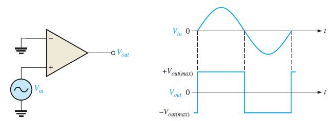
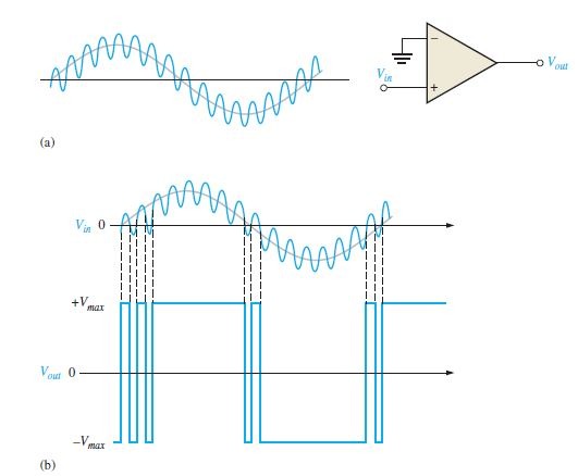
As the name indicate zero level detector detects when ever input signal crosses zero level. Here input signal is connected to non inverting terminal and inverting terminal is grounded. Here we used a sinusoidal signal, during the positive half cycle of sine wave output will be constant positive value. During negative half output will be constant negative value. thus we will get a a square pulse is in the above figure.
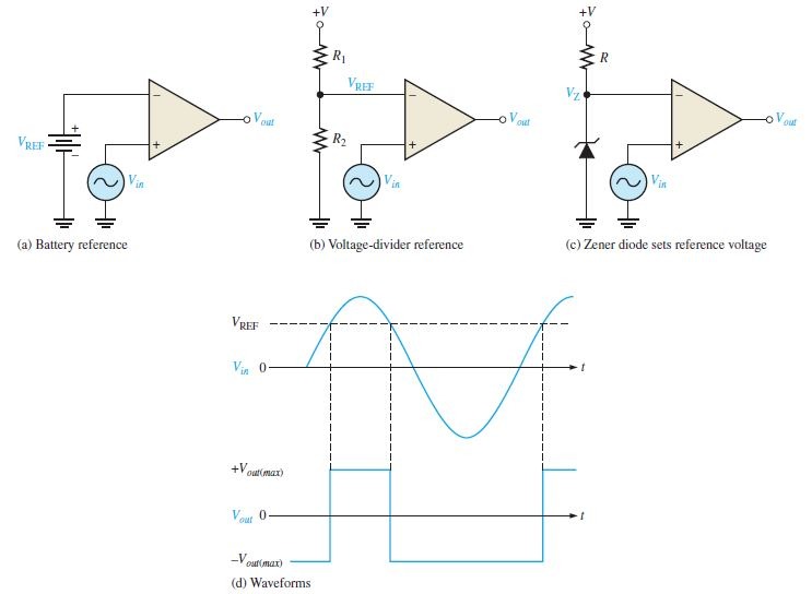
Non Zero-Level Detection, Op-amp comparator circuit
It is a modified version of zero level detector to detect positive signal. Instead of grounding inverting terminal, It is connected to a reference voltage.
This reference voltage can be applied in three different ways.
- Battery reference
- Voltage divider reference
- Zenor diode reference
Among this three references voltage divider reference is a more practical method.
Reference voltage of voltage divider is
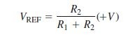
When ever the input signal increases its value greater than reference value a maximum positive value is generated at the output. otherwise it will remains at maximum negative value as shown in the figure.
Effects of Input Noise on Comparator Operation
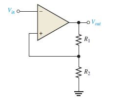
Noise is unwanted signal. which is practically present in every signals. This presence will effect the output of comparator. Noise superimpose with input signal to form a slightly different signal. But this slight variation will effect output.
Consider a zero level detection, a slight variation in input signal will effect the output pulse, Resulting an error. This unstable condition occurs when the input voltage hovers around the reference voltage, and any small noise fluctuations cause the comparator to switch first one way and then the other.
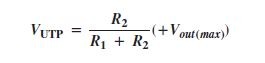
Reducing Noise Effect in Comparator with hysteresis
Error due to noise in input signal results error in output. This error can be rectified with the aid of positive feedback which results in hysteresis. Hysteresis is that there is higher reference level when input voltage increases from smaller to higher value and lower reference level when input decreases from higher to lower level. This two reference levels are upper trigger point (UTP) and the lower trigger point (LTP).
for hysteresis.
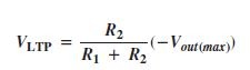
A comparator with built-in hysteresis is called Schmitt trigger. The amount of hysteresis is the difference between this two trigger levels.
Output Bounding in comparator
In some applications we have to reduce the output of comparator below saturation for that output bounding can be used by simply a single zenor diode.
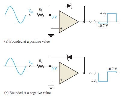
In case of bounding in positive value. positive (anode) part of the zener diode is connected to the inverting terminal and negative part to output. Input signal is connected to inverting terminal and non inverting terminal is grounded. thus inverting terminal is virtual ground. Therefore when the output voltage reaches a positive value equal to the zener voltage, it limits at that value. Which we can see in the above image.
Similarly for comparator bounded at negative value cathode of zener is connected to inverting terminal and anode is connected to output. rest are similar to previous case. Here when the output voltage reaches a negative value equal to the zener voltage, it limits at that value.
Double bounded comparator
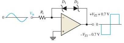
Two zener diodes are connected as shown in the above figure. Thus we get an output as a pulse with equal positive and negative half cycle. which is equal to sum of the zener voltage and forward voltage drop (0.7V) .