The wien bridge oscillator is a type of RC oscillator, that produces the sinusoidal output. It is commonly used in audio and Sub-audio frequency ranges, that is 20- 20KHz. The maximum frequency of the output of a wien bridge oscillator is only about 1MHz.
Contents
Circuit Diagram explanation of WIEN BRIDGE OSCILLATOR
It has two stage RC amplifier each producing a phase shift of 180 degree and thus producing a total phase shift of 360 degree or 0 degree.

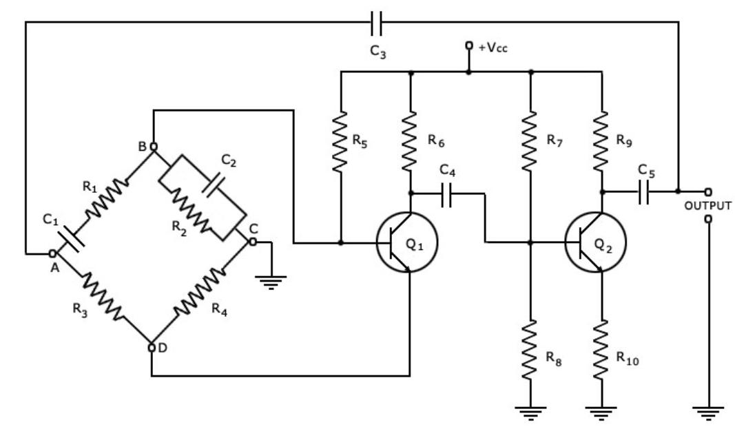
Figure shows the circuit of a wien bridge oscillator. It consists of two stage amplifier with a RC bridge circuit. The RC bridge circuit is a lead-lag network. The phase shift across the network lags with increasing frequency and leads with decreasing frequency. Because of the wien bridge feedback network, the oscillator Will be sensitive to a signal of only one particular frequency, at which wien bridge is balanced and phase shift is 0 degree. If the bridge network is not employed and direct coupling from output of transistor Q2 to input of transistor Q1 is employed, the transistor Q1 amplify signal over a wide range. It results in poor frequency stability.
Functions of resistors and capacitors in the circuit
The diagram shows resistor R1 is in series with C1, R3, R4 and resistor R2 is in parallel with C2 to form the four arms. The output of the second stage amplifier is supplied back to the feedback network and the voltage across the parallel combination C2 R2 is fed to the input of the first stage. The transistor Q1 serves as an oscillator and amplifier, whereas the transistor Q2 as an inverter to cause a phase shift of 180 degree. The circuit have positive and negative feedback. The positive feedback is through R1, C1, R2 & C2 for transistor Q1 and negative feedback is through the voltage divider to the input of transistor Q1. Resistor R3 & R4 are used to stabilize the amplitude of the output.
Click here to know about trending new technologies in electronics field
Frequancy of generated signal
At very low frequencies the output voltage becomes zero, since the series capacitor behaves as an open circuit and also there is no output at very high frequencies since the parallel capacitor acts as short circuited path to the input voltage. Therefore in between these two extreme conditions, the output voltage reach to the maximum value.
The resonant frequency at which the bridge is balanced under the condition that R1=R2 = R and C1=C2=C is given by,
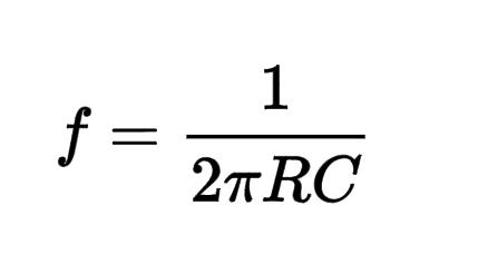
And R3=2R4
At this frequency, feedback network attenuates the output voltage by a factor of 1/3. This means that the voltage gain shall be equal to or greater than 3.
OPERATION OF wien bridge oscillator
The circuit is set in oscillations by any change in base current of transistor Q1, due to variation in voltage of DC supply. The variation in base current is amplified the transistor Q1 with a phase shift of 180 degree. The output of transistor Q1 is fed to the base of second transistor Q2 through capacitor C4. The signal is again amplified and phase reversed by 180 degree by the transistor Q2. Because of inverted twice, the output signal will be in phase with the signal input to the base of transistor Q1.
The output signal at the transistor Q2 is feedback to the input points of the bridge circuit A to C. A part of this feedback signal is applied to emitter resistor R4, which gives the negative feedback. Similarly, a part of this feedback signal is applied across the base biased resistor R2 which provides the positive feedback.
The continuous frequency variation in this oscillator can be had by varying the two capacitors C1 & C2 simultaneously, which are variable air – gang capacitors. The frequency range of oscillator can be varied by changing the values of resistors R1 & R2.
ADVANTAGES OF wien bridge oscillator
- It provides a stable low distortion sine wave output over a wide range of frequencies.
- The frequency of oscillation can be easily varied by varying capacitance C1 & C2 simultaneously.
- The frequency range of oscillator can be simply varied by changing resistors R1& R2.
- The overall gain is high because of two transistors.
- It is useful in audio frequency i.e 20 Hz to 100 KHz
DISADVANTAGES OF wien bridge oscillator
- It requires two transistors and large number of other components, hence it increases the cost.
- The maximum frequency output is limited because of amplitude and phase shift characteristics of the amplifier
APPLICATIONS OF wien bridge oscillator
- Used for distortion testing of power amplifier
- To supply the signals for testing filters
- Used to give excitation for AC bridge
- Fabricate pure tune
- Measure the audio frequency
created by : Anju Radhakrishnan
Image courtesy : Google image