Picture courtesy : google
Schmitt trigger is an electronic circuit with positive feedback which converts a sinusoidal or any analog signal to digital signal. Schmitt trigger is a comparator circuit with hysteresis, that is the output transition from high to low and low to high will occur at different thresholds.
Schmitt trigger belongs to the class of bistable Multivibrator, which have two opposite operating states. Schmitt trigger is level sensitive and the output switches between two trigger levels, Lower Trigger Level (LTL) and Upper Trigger Level (UTL).
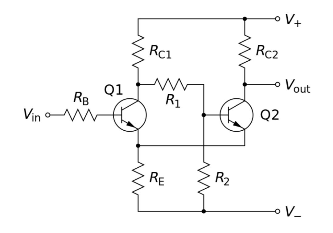
Figure shows the circuit of a Schmitt trigger. It contains two identical transistors Q1 and Q2 coupled through an emitter resistance RE. The output of transistor Q1 is coupled to the input of transistor Q2 through resistor R1.
WORKING of SCHMITT TRIGGER
When the power is applied to the circuit, the resistor R1, R2 and RE forming a potential divider across Vcc and ground. Which slightly forward biases the transistor Q2 and Q2 start conducting. The current flows through Resistor RE and it produces a voltage drop across it. Because of this voltage drop, transistor Q1 is reverse biased and drives to cutoff. Then the collector voltage of transistor Q1 rises towards Vcc and this rising voltage is coupled to the input of transistor Q2 through resistor R1. This drives transistor Q2 further into saturation and holds there.
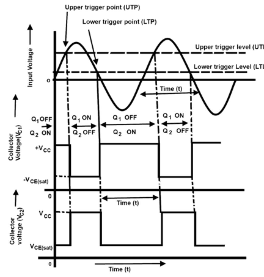
When an input AC signal is applied to the base of transistor Q1, as it is increases to the voltage sufficient to overcome the reverse bias of transistor Q1 or reaches above the upper trigger level, the transistor Q1 starts conducting. The point at which the transistor Q1 start conducting is called Upper Trigger Level(UTL) . when the transistor Q1 starts conducting, the voltage drop at the collector of Q1 drops to minimum. This negative going signal is coupled to the base of transistor Q2 through resistor R1 reduces it’s forward bias and thus emitter current , and hence the voltage drop across resistor RE. As a result reverse bias of transistor Q1 reduces and conducts more. Thus the collector voltage of transistor Q1 drops and transistor Q2 further driven into cutoff. This process continue till transistor Q1 driven into saturation and transistor Q2 into cutoff.
After a half a cycle of the input AC signal, it will be negative going. The transistor Q2 continue in cutoff till the input voltage falls below the lower trigger level. When it crosses LTL , transistor Q1 becomes reverse biased due to negative going input signal. As a result the collector voltage of transistor Q1 rises towards Vcc and it is applied to the base of transistor Q2 through resistor R1. This makes transistor Q2 to conduct. The point at which transistor Q2 start conducting is called Lower Trigger Level (LTL). When the transistor Q2 start conducting, voltage drop across resistor RE increases and it drives transistor Q1 in to cutoff. This state continue till the input AC signal again crosses the Upper Trigger Level. Therefore a positive going pulse is generated at the output.
This completes one cycle and is repeated as the input AC signal repeats it’s cycle.
APPLICATIONS of SCHMITT TRIGGER
- Used in signal conditioning applications to remove noise from signals in digital circuits.
- Used as squaring circuit.
- Used as amplitude comparator or level detector.
- Used as flip-flop circuit.
- Used for reshaping the worn out pulses.
- Used to implement relaxation oscillator in function generators and switching power supplies.
Click here for Schmitt trigger using Opamp
created by technical writer : Anju Radhakrishnan