In this post, we are going to talk about the Schmitt Trigger using opamp. And we will understand what is this Schmitt Trigger, what is the purpose of using this Schmitt Trigger in electrical and electronics systems, and how it can be designed.
Contents
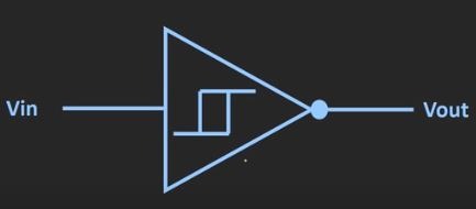
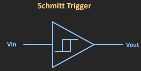
Schmitt Trigger – Introduction
Schmitt Trigger, Avoids the problem in comparator
Now, in the previous post of the comparator, we have seen that it can be used to compare the two voltage levels. But the problem with this comparator is that if the input signal is noisy, in that case, your output will be get affected. And you will not get the desired output.
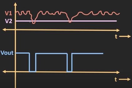
let’s say we have one comparator and to this comparator, we have applied these input signals V1 and V2. Now, here assume that this signal V1 is the input signal and this signal V2 is the reference signal. assume that these signal are ideal signals. in that case, as V1 is greater than V2. so you should get constant high output voltage. But if this signal V1 is noisy, in that case, it is possible that it can affect your output voltage.

Because of the noise, this V1 signal looks like this (Find above graph). If you observe this signal V1, then you can notice that this signal V1 crosses this signal V2 at two locations. for the time period for which this signal V1 is less than V2, for that duration you will get low voltage. because of the noise, you will see the transition in the output voltage. Or we can say that output will be get affected because of the noise in this input signal. Thus, we can say that this comparator is not immune to the noise. And because of that, it can affect your output.
This kind of problem can be avoided by using the Schmitt Trigger. Now, this Schmitt Trigger is nothing but the comparator with the hysteresis. It means that this Schmitt Trigger has two threshold voltages. One is the upper threshold voltage, that is for low to high transition. second is the lower threshold voltage, that is for high to low transition.
Schmitt Trigger circuit Working
let’s say the signal which is represented in red color (above figure) is the input signal. And these two are the upper and the lower threshold voltage for the given Schmitt Trigger. now let’s see how this Schmitt Trigger will respond to this given input signal. And here, let’s assume that the initial voltage across this Schmitt Trigger is zero. So, as you can see over here, initially the input signal is zero, and gradually it is increasing.
The output of this Schmitt Trigger will remain low till the point this input signal crosses this upper threshold voltage. So, up to this point, your output signal will remain zero. And from that point onwards, your output signal will remain high.
once this input signal crosses this upper threshold voltage, then after it deviates around this upper threshold voltage. But then also, your output signal will remain high. And it will go to the low voltage only when this input signal goes below this lower threshold voltage. So, at this point, once again your output will become low. And it will remain low till the point this input signal crosses this upper threshold voltage. So, again at this point, your output will become high. And it will remain high after that point.
Even if your input signal varies around this upper and the lower threshold voltage then also your output signal will not get changed. And it will remain constant. So, we can say that this Schmitt Trigger provides the noise immunity over this band.
Hysteresis voltage of the Schmitt Trigger
The difference between this upper and the lower threshold voltage is known as the hysteresis voltage of the Schmitt Trigger. So, basically, this hysteresis voltage defines the noise immunity of the given Schmitt Trigger.
If you observe this example, there are four parameters which are required to define the Schmitt Trigger. The first two are high and the low output levels of the Schmitt Trigger and the remaining two are the upper and the lower threshold voltages, which will decide the triggering instance for the Schmitt trigger. So, these four parameters define the characteristics
of the Schmitt Triggers.
Characteristics of Schmitt Trigger
The characteristics of the Schmitt Trigger graphically can be represented by this transfer characteristic curve. So, here on the X-axis, we have input voltage and on the Y- axis we have the output voltage. now for the given example, let’s draw the transfer characteristic of the Schmitt Trigger. if your input signal is less than the upper threshold voltage level of the Schmitt Trigger, in that case, your output will remain low.
And as soon as it crosses this upper threshold voltage level then your output will become high. if the input signal goes beyond this upper threshold voltage level then also your output will remain high. Now, suppose if your input signal starts reducing then also your output signal will remain high. it will remain high till the point your input signal goes below this lower threshold voltage level. as soon as your input signal goes below this lower threshold voltage then again your output will become low voltage.
if your input signal goes below this lower threshold voltage then also your output will remain low. this is how the Schmitt Trigger can be represented using this transfer characteristics. So, this transfer characteristic is also known as the hysteresis curve for the Schmitt Trigger. if your output voltage levels VHand VL are equal and opposite in polarity, in that case, your transfer characteristics curve will be symmetric with respect to the Y-axis.
Non-inverting Schmitt Trigger
By providing the reference voltage as an input to this Schmitt Trigger, we can shift this curve either to the right or the left-hand side. So, for the Schmitt Trigger, which has this kind of transfer characteristic curve is known as the non-inverting Schmitt Trigger. Because here, once your input signal crosses this upper threshold voltage level then your output will become high and when your input signal is less than this lower threshold voltage, at that time your output will become low.
Thus we can say that this transfer characteristic curve is the curve for the non-inverting Schmitt Trigger.
Inverting Schmitt Trigger
Similarly, we can have hysteresis curve for the inverting Schmitt Trigger. in case of this inverting Schmitt Trigger. whenever your input signal is less than the upper threshold voltage level at that time your output will be high. And once, it crosses the upper threshold voltage level, then your output will become low voltage. And if we go beyond this upper threshold voltage level, then also your output will remain low.
suppose this input signal starts reducing then also your output will remain low. And it will remain low till the point your input signal crosses the lower threshold voltage level.This input signal crosses this lower threshold voltage level, then once again your output will become high. this is the transfer characteristic curve of the inverting Schmitt Trigger. This curve can be shifted either to the right or left side by providing the external reference voltage as an input to this inverting Schmitt Trigger.