picture courtesy : Google
BISTABLE MULTIVIBRATOR
Bistable Multivibrator or two-shot Multivibrator have two stable state, that’s why the name bistable Multivibrator. It will flipped from one stable state to another stable state by external trigger pulse. It requires two trigger pulses. In the application of first trigger pulse circuit will switches from one state another and continue the state till another trigger pulse is applied. When the second trigger pulse is applied, the circuit will returns to it’s original stable state.
Bistable Multivibrator is also called flip-flop Multivibrator because, the circuit flips from one state to another state, remains there and flops to it’s original state.
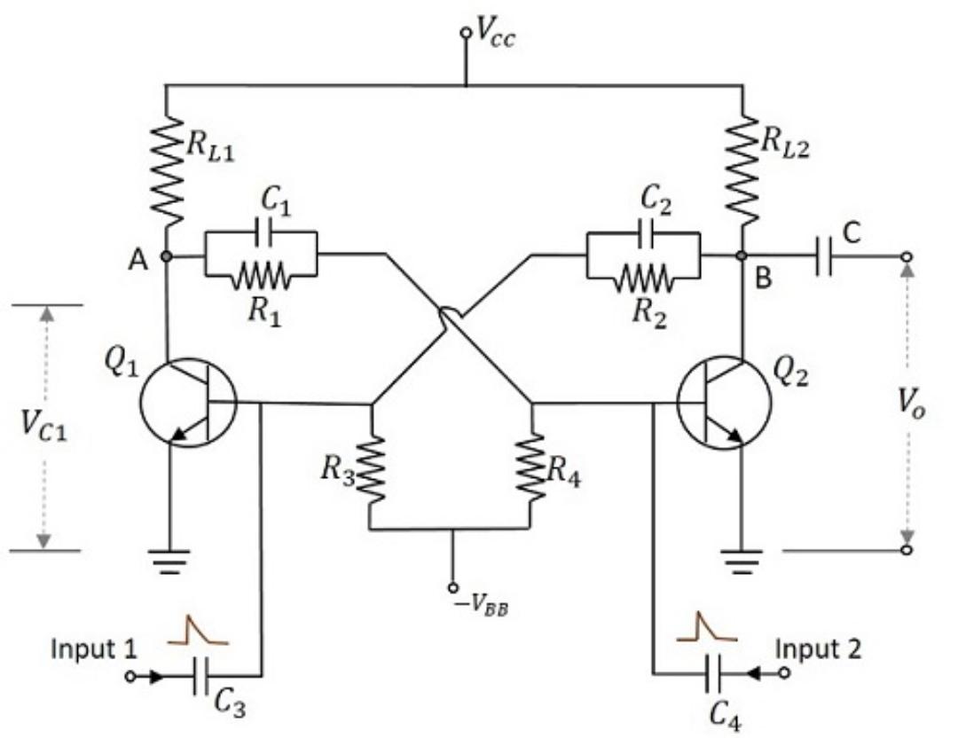
Circuit of a bistable Multivibrator using two NPN transistor is shown in figure it have two identical transistors Q1 and Q2 with equal collector resistances RL1 and RL2. The output of transistor Q1 is coupled to the input of transistor Q2 through resistor R1 and the output of transistor Q2 is coupled to the input of transistor Q1 through Resistor R2. The feedback resistors are shunted by capacitors C1 and C2. These capacitors are known as commutating capacitor and is employed to improve the switching characteristics of the circuit. Thus the transition time is reduced and distortionless output is obtained.
WORKING
When the power gets on, one transistor conducts slightly more than the other transistor due to differences in their characteristics. Suppose transistor Q1 conducts more and it drives in to saturation mode. Then the voltage at the collector of Q1 drops to minimum and this reduced voltage is coupled to the base of transistor Q2 through resistor R1. This drives transistor Q2 in to cutoff. Then the collector voltage of Q2 rises towards Vcc. This rise in voltage is coupled to the input of transistor Q1 and this makes transistor Q1 further saturated. This is the first stable state of the Multivibrator. That is Q1 ON and Q2 OFF.
The circuit remains in it’s first stable state until a positive trigger pulse is applied to the base of transistor Q2 or a negative trigger pulse is applied to the base of transistor Q1.
Suppose a positive trigger pulse is applied to the base of transistor Q2 through capacitor C2. This reduces the reverse bias on transistor Q2 and drives it in to saturation. It causes voltage drop at collector of Q2 to drops minimum and this decreasing voltage is applied to the base of transistor Q1 through Resistor R2. This drives the transistor Q1 into cutoff. Then the voltage at the collector of Q1 rises towards Vcc and this rise in voltage is fed to the base of transistor Q2 through resistor R1. This drives transistor Q2 further into saturation even if the trigger is removed . This is the second stable state of the Multivibrator. That is Q1 OFF and Q2 ON.
The circuit will remains in it’s second stable state until a positive trigger pulse is applied to the base of transistor Q1 or a negative trigger pulse is applied to the base of transistor Q2.
The output obtained at the collector terminals of Q1 and Q2 are complementary to each other always.
APPLICATIONS
- Used for counting and storing the binary information
- Used as frequency divider in timing circuits
- Used for generation of clock pulses
- Used in relay controllers
- Used as electronic toggle switch
Created by Anju Radhakrishnan