Voltage regulation is classified into line regulation and load regulation. In line regulation output voltage is regulated when the input voltage changes. The purpose of load regulation is regulating output voltage when theload changes.
Contents
Line Regulation
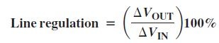
Line regulation can be defined in percentage and percentage per volt (%/V). To define Line regulation in percentage, it is the ratio of change in output voltage to change in input voltage.
Line voltage can also explained in percentage per volt (%/V)
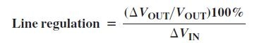
If line regulation in percentage per volt is 0.10%/V means that the output voltage changes 0.10 percent when the input voltage increases
or decreases by one volt.
Load Regulation
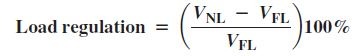
As the load varies, load current changes thus output voltage changes. This change is independent to input signal. This should be reduced to a negligible value. load regulation is the solution for this problem. Load regulation can be defined as the percentage change in output voltage for a given change in load current or load resistance. load regulation can also explained as a percentage change in output voltage from no load (NL) to full load (FL).
If load regulation of a circuit is 0.05%/mA, It means that the output voltage changes 0.05 percent when the load current increases or decreases by 1 mA. Sometimes power supply manufactures mention output resistance instead of load regulation. Load regulation can be calculated from output resistance.
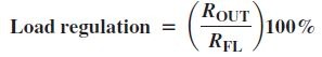
Load regulation is also defined as the percentage of ratio of output resistance to full load resistance.
Linear and Switching voltage regulator
Voltage regulators are again classified as linear regulator and switching regulators. Both of them are also available as integrated circuits.
Linear Voltage Regulator
linear voltage regulator is of two types, namely series regulator and the shunt regulator.
Linear Series Voltage regulator
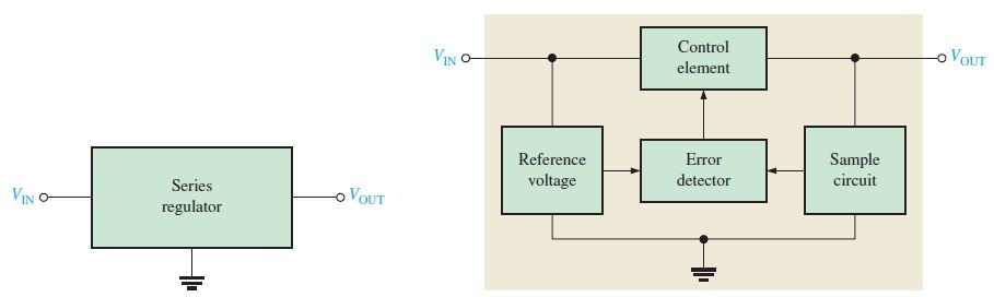
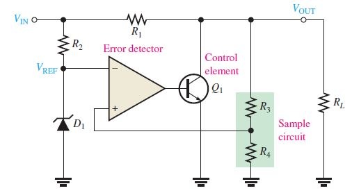
Linear Series Voltage regulator
As shown in the above figure their is a control element between input and output. Error detector detects error by comparing reference voltage with sample voltage. Its comparison result is feed to control element which maintain a constant output voltage.
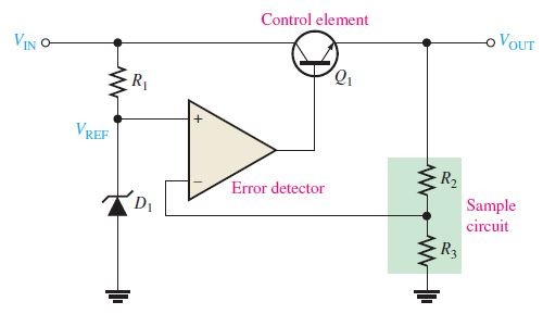
Transistor is used as the control element and op-amp is used error detector. reference voltage is generated by using a zener voltage regulator.Out put voltage can be represented as,
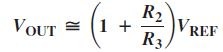
From this equation, it is evident that output only depends on sample circuit resistors and zener diode. That is, it would not change with input voltage, so regulation achieved.
Short-Circuit or Overload Protection – If an excessive amount of load current is drawn, control element ( series-pass transistor ) will quickly destroyed. To protect this resistor a current-limiting mechanism is required. Such a protection method is shown in the below figure. This protection method is called constant-current limiting.
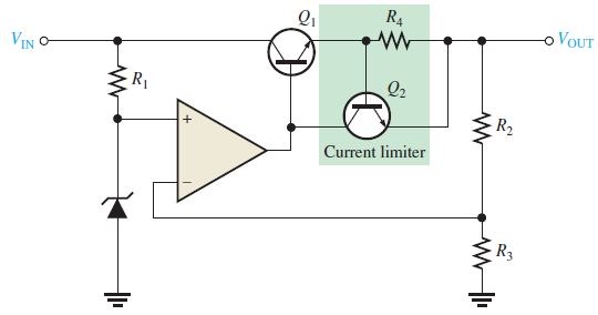
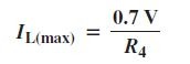
maximum limiting current is
Another method for overload protection is called fold-back current limiting. This method is used in high-current regulators whereby the output current under overload conditions fold back to a value well below the peak
load current, It will prevent excessive power dissipation.
Linear Shunt Voltage Regulator
Linear series voltage regulator, have a transistor connected in series with the load to limit excess load current. Here a transistor is connected parallel to the load (shunt).
Linear series voltage regulator
As shown in the figure, control element is a transistor, in parallel with the load. A resistor, is in series with the load. Its working is similar to that of the series regulator, except that regulation is achieved by controlling the current through the shunt transistor. When ever output voltage decreases due to change in the input voltage or load current, sample circuit sense it and feed to opamp and thus control element increases output voltage to ensure that it is regulated.
Similarly sample circuit sense when output voltage increases beyond the required voltage and feed it to opamp. opamp in turn activate control element to control the change in output. The shunt regulator is less efficient than the series regulator. But offers short-circuit protection.
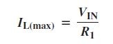
Maximum limited current by shunt regulator is,
Switching Regulator
Linear regulators discussed above is of two types, series and shunt. Both have control elements (transistors). These transistors are conducting all the time. Amount of conduction varied according to the changes in the output voltage or current. But in Switching regulator control element in act as a switch. So great efficiency can be achieved with the switching regulator than linear regulator, the transistor switches on and off and dissipates power only when it is on. All switching regulators require feedback to control the on-off time .
Switching regulators have about 95 % efficiency. Thus it is useful when efficiency is important. Where as linear regulators act as a variable resistor, generate heat and power dissipation increases to a great extend. Switching regulators are designed for various power levels. It ranges from less than one watt to hundreds and thousands of watts. Required regulator is chose according to the application.
Three basic configurations of switching regulators are step-down, step-up, and inverting.
- Step down
- Step up
- Inverting
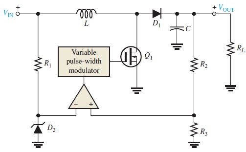
Step-Down Configuration
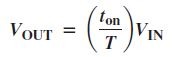
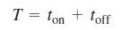
Step-down configuration is also known as a buck converter. The output voltage of Step-down is always less than the input voltage. The basic control element is a high-speed switch, which works rapidly. It senses the output from a control circuit and adjusts on time and off time to get the desired output.
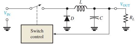
When the switch is closed, diode is off and the magnetic field of the inductor increases and energy storing takes place. When the switch opens, the magnetic field decreases, results in constant current in the load. The capacitor in the figure makes the DC to a nearly constant level. load resistance should not too large, otherwise diode never become forward biased.
Mostly MOSFET is used as switching device. because it is more rapid than BJT. Sometimes Thyristors are also used as switching devices, but its rare.
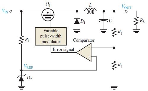
LC circuit in the above figure smooths pulse from the transistor. Inductor makes the current constant and capacitor makes the voltage constant. Higher switching frequency ( much higher than the utility frequency ) is used to avoid requirement of large and expensive capacitors and inductors. 20 kHz is commonly used as switching frequency. But using higher frequency causes electrical noise. Switching power supplies radiate harmonic frequency noise to nearby circuits, so they are well shielded
and EMI (electromagnetic interference) filters are used.
Output voltage of step up configuration,
Step-Up Configuration
Step-up configuration is also known as a boost converter. The output voltage of Step-down is always greater than the input voltage. The basic control element is a high-speed switch, which works rapidly. It senses the output from a control circuit and adjusts on time and off time to get the desired output.
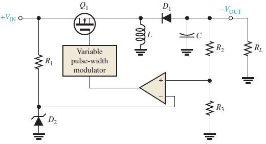
Voltage-Inverter Configuration
Voltage-Inverter Configuration is also known as buckboost converter. This third type switching regulator produces an output voltage opposite in polarity to the input.
Integrated Circuit Voltage Regulators
We already discussed about the basic voltage regulator configurations.
This section deal Integrated Circuit Voltage Regulators. There are several types of linear and switching regulators are available in the form of integrated circuit (IC).
Generally, the linear regulators are three-terminal devices. It provide
either positive or negative output voltages. This can be either fixed or adjustable.
Fixed Positive Linear Voltage Regulators
78XX series is a Fixed Positive Linear Voltage Regulator. It is a three-terminal devices, which are input, output, and ground as indicated in the
below figure.
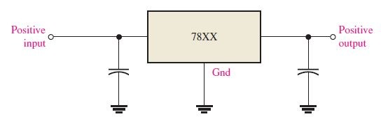
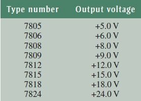
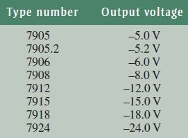
The last two digits in the part number designate the output voltage.
Fixed Negative Linear Voltage Regulators
79XX series is a Fixed negative Linear Voltage Regulator. It is a three-terminal devices, which are input, output, and ground as indicated in the
below figure.
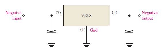
79XX series
Adjustable Positive Linear Voltage Regulators
LM317 is an adjustable positive linear voltage regulator. It is a three-terminal devices, which are input, output, and an adjustable terminal to adjust output voltage. LM317 can vary its out put from 1.2 V to 37 V.
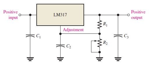
positive voltage regulator
The capacitors are for decoupling and do not affect the dc operation. resistors R1 and R2 in the output section is used to adjust the output, where R1 is fixed and R2 is adjustable.
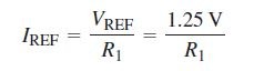
Vref = voltage across R1
LM317 is a “floating” regulator because the adjustment terminal is not connected to ground.
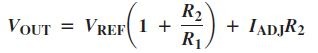
Adjustable Negative Linear Voltage Regulators
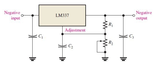
LM337 is an adjustable negative linear voltage regulator. Like LM317, It is a three-terminal devices and two external resistors for output voltage adjustment. LM337 can vary its out put from – 1.2 V to – 37 V.